Labs on Video: Analyze Digitally Modulated 16-QAM & 64-QAM
Objectives
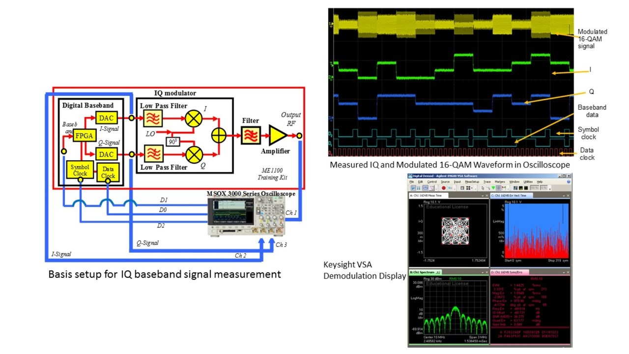
i) To study the digitally modulated quadrature amplitude modulation (16-QAM and 64-QAM) waveforms using an oscilloscope
ii) To demodulate the modulated 16-QAM and 64-QAM signals using the VSA software
iii) To measure the error vector magnitude (EVM) of the modulated 16-QAM and 64-QAM signals using an oscilloscope and the VSA software
Introduction of Quadrature Amplitude Modulation
EVM (Error Vector Magnitude)
In vector modulation, digital bits are transferred onto an RF carrier by varying the carrier’s magnitude and phase. At each symbol clock transition, the carrier occupies any one of several unique locations on the I versus Q plane. Each location encodes a specific data symbol, which consists of one or more data bits. A constellation diagram shows the valid locations (i.e., the magnitude and phase relative to the carrier) for all permitted symbols of which there must be 2n, given n bits transmitted per symbol. To demodulate the incoming data, the exact magnitude and phase of the received signal for each clock transition must be accurately determined.
The layout of the constellation diagram with its ideal symbol locations is determined generically by the selected modulation format (BPSK, QPSK, etc.). The trajectory taken by the signal from one symbol location to another is a function of the specific system implementation, but is readily calculated nonetheless.
At any moment, the signal’s magnitude and phase can be measured. These values define the actual or “measured” phasor. At the same time, a corresponding ideal or “reference” phasor can be calculated, given knowledge of the transmitted data stream, symbol-clock timing, baseband filtering parameters, etc. The differences between these two phasors form the basis for the EVM measurements. Figure 1 defines EVM and several related terms.
As shown in Figure 1, EVM is the scalar distance between the two phasor end points, i.e., it is the magnitude of the difference vector. Expressed in another way, it is the residual noise and distortion remaining after an ideal version of the signal has been stripped away. In the QPSK modulation format, these symbols all have the same voltage level, though this is not true for all formats. EVM could be defined differently for other modulation formats. In a format such as 64QAM, for example, the symbols represent a variety of voltage levels. EVM could be defined by the average voltage level of all the symbols (a value close to the average signal level) or by the voltage of the outermost (highest voltage), four symbols. While the error vector has a phase value associated with it, this angle generally turns out to be random because it is a function of both the error itself (which may or may not be random) and the position of the data symbol on the constellation (which, for all practical purposes, is random). A more useful angle is measured between the actual and ideal phasors (I/Q phase error), which contains information useful in troubleshooting signal problems. Likewise, the I-Q magnitude error shows the magnitude difference between the actual and ideal signals. EVM, as specified in the standard, is the root-mean-square (RMS) value of the error values at the instant of the symbol-clock transition. Trajectory errors between symbols are ignored.
To view how the lab exercise is carried out in a lab environment, please view the DreamCatcher Digital Modulation Techniques Courseware’s lab-on-video:
You may also like to download the lab sheets which the video is based on. Sample Lab Sheet
To learn more about ME1110-Digital Modulation Techniques Teaching Solutions, please log on to: http://dreamcatcher.asia/cw/products/1110?scroll=1
You may also like to register with us to receive future article: signup newsletter