A Novel 64 QAM-OFDM Optical Access System Based on Bit Reconstruction
by
 , , ,
, , ,
Rongzhen Xie
1, 
Di Wu
1,
Qi Zhang
1,2,3,*,
Haipeng Yao
1,2,3,
Xishuo Wang
1,
Xiangjun Xin
4,
Feng Tian
1,2,3,
Qinghua Tian
1,2,3,
Fu Wang
1,2,3,
Yongjun Wang
1,2,3,
Leijing Yang
1,2,3 and
Jinkun Jiang
1 1
School of Electronic Engineering, Beijing University of Posts and Telecommunications (BUPT), Beijing 100876, China
2
Beijing Key Laboratory of Space-Ground Interconnection and Convergence, BUPT, Beijing 100876, China
3
State Key Laboratory of Information Photonics and Optical Communications, BUPT, Beijing 100876, China
4
The Advanced Research Institute of Multidisciplinary Science, Beijing Institute of Technology, Beijing 100081, China
*
Author to whom correspondence should be addressed.
Photonics 2023, 10(8), 879; https://doi.org/10.3390/photonics10080879
Submission received: 14 June 2023
/
Revised: 12 July 2023
/
Accepted: 21 July 2023
/
Published: 28 July 2023
(This article belongs to the Special Issue Next-Generation Passive Optical Networks: Progress and Challenges)
Abstract
:This paper proposes a novel orthogonal frequency division multiplexing (OFDM) optical access scheme based on bit reconstruction. In this method, correlation is introduced into the data information of optical line terminals (OLT) through the logical coding circuits and partition mapping. Even after passing through the optical fibre channel, the strong correlation after bit reconstruction can still be used in the optical network unit (ONU) for reliable decoding. In the simulation experiments, a 60 Gbit/s bit reconstruction 64 quadrature amplitude modulation (QAM) OFDM signal was successfully transmitted over a 10/20 km single-mode fibre (SMF). The simulation results show that the proposed scheme can effectively achieve reliable transmission with gains of about 1.3 dB and 0.51 dB at a 20% soft decision-forward error correction (SD-FEC) threshold, respectively. The proposed scheme is a promising candidate for a next-generation passive optical network (NGPON) solution.
1. Introduction
Recently, with the rapid development of cloud computing, Internet of Things (IoT), fifth generation mobile communication systems (5G) [1,2,3,4,5], and the recent rise in sixth generation mobile communications (6G) [6,7], the demand for high-speed and reliable data transmission is increasing. This also means that the optical access network is facing a huge challenge of capacity expansion [8] Facing the multiple demands of future communication systems, PON technology with low cost and high bandwidth is the most promising solution for future optical fibre access, termed the “last kilometre”. The evolutionary direction of NG-PON2 has also become a hot topic of discussion in international standards organizations such as ITU-T and FSAN [9,10]. PON has proven to be an efficient and future-proof network architecture with strong advantages [11,12]. Considering the high requirements of system cost, compatibility, and complexity of PON, researchers have turned their attention to OFDM-PON [13,14]. The introduction of OFDM technology in the field of optical communication technology is a divisive innovation. On the one hand, it can be used as a modulation technique to improve the spectrum utilization and channel capacity of the channel, and it can effectively counteract multipath and dispersion effects. On the other hand, it can be used as a subcarrier to achieve efficient OFDMA access, thus enabling flexible bandwidth allocation for multiple users and services. Different subcarriers can be assigned to different users as well as different service types, such as TDM, FTTH, FTTB, mobile base stations, etc. [15,16]. These characteristics of OFDM technology make it particularly suitable for application in access networks, with its service scheduling and flexibility. Recent internet access and traffic have greatly increased, and it is foreseeable that future communication system application scenarios will require higher data rates and a greater transmission capacity. For standard SMF optic transmission systems, multi-carrier modulation technology is an important means of system expansion [17]. At the same time, OFDM has a stronger dispersion robustness than the single-carrier modulation format, reasonably modulating the spectrum according to the characteristics of the subcarrier channel. It can achieve broadband optical access above 40 Gb/s with flexibility [18]. Because of its excellent digital signal processing characteristics and high spectrum utilization, OFDM optical access technology is widely used in access systems, so the advantages are even more obvious.
Typically, OFDM technology is preferred for optical access systems; however, it brings some unavoidable problems. There is a high peak factor in the OFDM modulation which increases the complexity of digital-to-analogue converters (DACs) and analogue-to-digital converters (ADCs). Nageswaran et al. proposed a comprehensive non-linear compression–expansion technique to improve the discrete chord transform, effectively reducing the peak to average power ratio (PAPR) of the system [19]. Concomitantly, the OFDM system is very sensitive to phase noise and carrier frequency offset, causing inter-symbol interference (ISI). Xin et al. innovatively proposed a robust decision feedback equalizer (DFE) for the OFDM system to overcome the serious ISI problem [20]. XuXing et al proposed a probabilistic shaping passive optical network technology based on symbol-level labelling and rhombus-shaped modulation, making deployment of the optical access networks flexible and robust [21]. This shows that some efforts have been put into the OFDM-PON to address the inherent effects of the system.
The traditional one-dimensional coded modulation technique has low bandwidth utilization filtration, while the orthogonal modulation technique uses two-dimensional coded modulation, where both the amplitude and phase can carry information bits to achieve efficient transmission. However, at a given transmission power, the Euclidean distance between the constellation points of high-order QAM modulation is smaller than that of the constellation points of low-order QAM modulation, and therefore the noise tolerance of the signal is reduced [22]. Compared to 4/16/32QAM, 64QAM has higher spectrum utilisation. The complexity of this implementation is simpler compared to systems with higher-order QAM modulation formats. Therefore, we chose the 64QAM-OFDM system as the approach to investigate.
In this paper, a novel 64QAM scheme suitable for an OFDM access network is proposed. Applying part of the response signal to the multi-amplitude modulation signal, the bit reconstruction part set in the OLT aims to generate a multi-level modulation signal and map the constellation according to the preset precept. The bit reconstruction portion realizes a strong correlation between the transmitter (TX) and the receiver (RX). According to the simulation results, compared with the general OFDM system, our project has a gain of about 1.3 dB and 0.51 dB at the threshold of SD-FEC (0.02) in a 10/20 km OFDM access system with 10 Gbaud transmission, respectively. Moreover, the system does not further deteriorate PAPR.
2. Theory and Principle
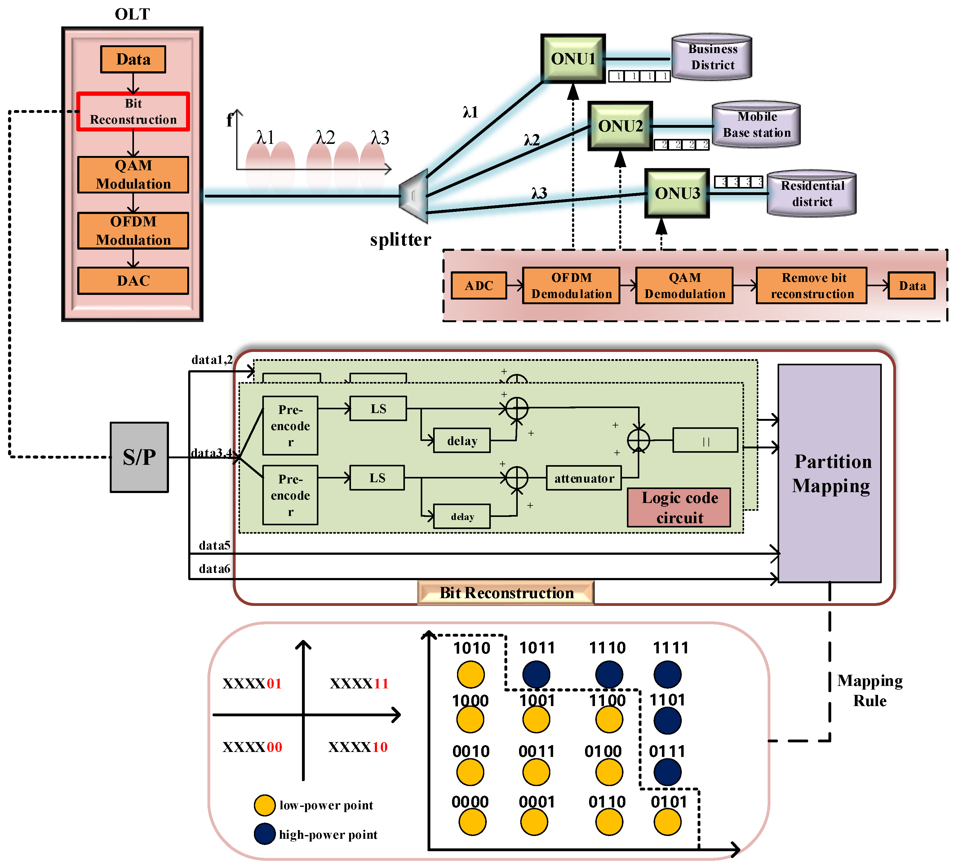
For the optical access system, the proposed 64QAM-OFDM optical transmission scheme is shown in Figure 1. In this scheme, channel multiplexing PON based on OFDM technology is adopted, and each ONU occupies a different orthogonal subcarrier. We form a strong correlation signal by reconstructing the information bit and use QAM modulation. On the OLT side, the transmission data are modulated by using OFDM technology. The modulated data is multiplexed to different subcarriers and then broadcast to different ONUs.
To enhance the reliability of the data transmission, this paper proposes a novel 64QAM-OFDM signal generation method through reconstruction in the time domain. The generation of bit reconstruction-based 64QAM-OFDM optical signals is shown in the “Bit Reconstruction” part of Figure 1.
In our proposed theory, the original data information at the transmitter side is serially transformed into a serial data stream of the same number as the modulation order. According to the modulation order M of the proposed scheme, the original information is divided into data(1,2), data(3,4), data5 and data6, as shown in Figure 1. The bit reconstruction unit consists of two parts, the logical code circuit and the partition mapping unit. The serial raw data stream needs to be grouped two by two before entering the logical code circuit, i.e., data(1,2), data(3,4), data5 and data6, where data(1,2) and data(3,4), are used as the input into the logical code circuit for the relevant coding. The output, which is a two-stage symmetric signal concerning the zero level, will be obtained by adding two unequal binary branches via an adder. This information is combined with the information of data 5 and 6 (not entered into the logical code circuit, but are directly added into the partition mapping unit) to achieve bit reconstruction after the filling bit.
We assume that the independent binary data are generated at the transmitter, whose symbol matrix P can be expressed as:
where denotes the signal generated over k time intervals. Then the bit reconstruction matrix G is defined as:
where represents the data processing of the corresponding element of the symbol matrix P by the bit reconstruction matrix G. The initialization matrix G is an all-in-one matrix. Noticed that the particularity of matrix G here, if the system modulation format is , rows and of G are set to 0. Here G refers to the initialized bit reconstruction matrix . In the bit reconstruction section, we can see that the last two groups of the input bit streams after grouping do not enter the logic code circuit for relevant coding but directly enter the partition mapping stage. The last two rows of the initialized bit reconstruction are set to 0, as shown in Equation (3), which keeps the ungrouped data streams in the signal matrix P (i.e., the data streams that do not enter the logic code circuit) from being controlled by the bit reconstruction matrix operation when the relevant operation is performed with the signal matrix P.
For our proposed method, the bit reconstruction matrix is initialized as follows:
In particular, “0” is not an assignment element, but rather denoting not dealing with elements in the same position when compared to the symbol matrix P.
As is shown in the bit reconstruction part of Figure 1, the pre-encoder, electric displacement, attenuator and electric adder are amalgamated to form the logic code circuit. The pre-encoder contains a logical NOT gate, logical XOR gate, and a delay circuit. We consider setting reference bits that are and at instance in the logic code circuits because of the presence of the delay unit. The value chosen can be logic 0 or logic 1. Different reference bit selections will also affect the output of the logic code circuit. represents the initial value of the delay stage in the logic code circuit. It belongs to the reference bit matrix, as does . The reference level matrices and are all set to zero matrices. As the bit stream enters the pre-encoder module, the symbol matrix P refers to Equation (4):
where P is the transmitted symbol matrix, is the pre-coded matrix and ⊕ is the logic XOR gate.
On the basis of the logic code circuit, when the signal passes through the level shifter (LS), the bit reconstruction matrix is updated: is compared with the initialization bit reconstruction matrix ; if , then ; if , then the elements in do not change.
is continually updated:
In the logical code circuit, there is a 6 dB electric attenuator component to divide the amplitude by half. Therefore, the elements in rows of are halved. After this, the row–column transformation of the bit reconstruction matrix is carried out, and every two rows are added as one channel to obtain a new matrix, . Here multilevel symbols are generated with amplitudes that range from 0 to 3 which can be referred to Equation (6). In particular, the above operations do not apply to the last two rows of the matrix.
It should be noted that the number of bit streams output after the logic code circuit is reduced to half. In order to map the constellations, we fill some bits and update . We then set the filling rule:
The updated is compared with the symbol matrix P, and the elements in the same position of the P matrix are processed according to the value of to obtain the bit reconstruction matrix :
The partition mapping selects the constellation mapping of the reconstructed signal by the segmentation rule. As shown in the partition mapping part of Figure 1, in order to simplify the complexity of the mapping transformation, symmetry design is performed. The first four bits remain unchanged after a two-stage logic code circuit, i.e., each quadrant has a symmetrical position with the same four bits, while dividing the high- and low-power regions. It is well known that in the constellation diagram of a QAM signal, the constellation points at locations closer to the origin have lower power. As shown in the mapping rule in Figure 1, the yellow spheres represent the constellation points in the low-power region and the blue spheres represent the constellation points in the high-power region. The logic code circuit makes the bits values that enter into the partition mapping, i.e., the bit reconstruction matrix , flow mostly to the low-level amplitude . Filling bits are necessary to achieve the partition mapping. In this process, ‘00’, ’01’ and ‘10’ will be assigned to low-level amplitudes. At this point the signal has a slightly higher probability of being mapped to the yellow-sphere region, which is closer to the origin of the constellation diagram than to the blue-sphere region. This is the rationale for the division between the high- and low-power areas. The last two bits of each symbol are maintained to be specific (the signals mentioned above that do not enter the logic code circuit). For example, the last two bits of each symbol from the first to the fourth quadrant are 11, 01, 00, and 10, respectively. Then the bit reconstruction is complete.
In the OFDM module, an I/Q modulator with two MZMs is used to load real part and imaginary part information of the OFDM signal. According to the transmission function of MZM [18], the output optical signal is:
where A is a constant, is the DC bias voltage of the MZM, is the half-wave voltage of the MZM, and and are the frequency and phase of the transmitting laser, respectively. Suppose that only subcarriers with frequencies and exist in the signal, and the amplitude is a bit reconstruction signal which is mapped. The and can be expressed as:
By defining and , we can obtain:
where is the optical modulation index, and is the phase offset point of the modulator. can represent the baseband signal and can be expanded by the first-order Bessel function. When , the linear mapping of the system is optimal, so the output optical OFDM signal can be approximated as:
Typically, TX side preprocessing is performed in the OFDM module. The specific process is to map the modulation signal to multiple subcarriers, and convert the frequency domain signal on the parallel subcarriers to the time domain through the inverse fast Fourier transform. The cyclic prefix is inserted before each OFDM symbol.
Finally, the time domain signals of multiple subcarriers are superimposed through the parallel–serial conversion to form the 64QAM-OFDM transmission signal in the OLT.
3. Simulation Setup and Results
In this section, simulation experiments are designed to verify the performance of the proposed bit reconstruction scheme. The left half of Figure 2 represents the OLT data transmission process and the right half represents the ONU data reception process. Short-distance transmission of a 10 Gbaud 64QAM signal over SMF in a coherent optical OFDM access system is established. Firstly, the pseudo-random binary sequence (PRBS) with a length of 60,000 is converted into six channels of information flow at the TX. Then the proposed bit reconstruction process is performed. After encoding mapping, the symbol sequence enters OFDM modulation. The optical signal source uses a 1550 nm light wave and splits into two mutually orthogonal light waves. By interacting on the MZM to produce a modulated optical signal, the two light waves are combined. Before being passed through the optical fibre link, the output optical signal passes through the VOA to reduce the signal power before transmission. The transmission link is composed of SMF, whose dispersion is 16.75 ps/nm/km and attenuation is 0.2 dB/km. At the RX, the optical signals are converted to electrical signals by a coherent receiver. The length of the CP is 16. The signal is captured through the coherent receiver. We remove the CP and convert the data into a parallel signal. Removing bit reconstruction occurs after FFT and QAM demodulation. The detailed parameters of the simulation system are shown in Table 1.
Figure 3 and Figure 4 indicate that the signal amplitude changes during the bit reconstruction process. The horizontal coordinate represents the signal length and the vertical coordinate represents the signal amplitude. The red circles show the specific amplitude of the signal during each process. The signal enters the bit reconstruction section by first performing a series–parallel transformation and grouping two by two, where the signal amplitudes are 0 and 1. Figure 3a depicts the amplitude of the signal after the NOT-gate in the pre-encoder stage. The original signal has amplitudes of 0 and 1, which are flipped after the NOT-gates. Figure 3b shows the amplitude change in the signal after the heterodyne gate in the pre-encoder stage. The previously mentioned reference bits are shown here. Figure 3c shows the amplitude after going through the level shifter. At this point, the signal amplitude changes from the previous unipolarity to bipolarity. Similarly, the reference bits are shown here too. Figure 3d and Figure 4a show the change in amplitude after the delayers. The bipolar signal amplitudes may produce amplitudes of with the delayers. After the attenuator, the signal amplitude becomes half of the original data as shown in Figure 4b. In Figure 4c, it can be seen that after the adder the original signal becomes a bipolar signal symmetrical about zero with a signal amplitude of . Figure 4d shows the final output signal of the logic coding circuit.
Depending on the structure of the logic coding circuit, the input raw signal varies with the structure of the circuit. Starting from an initial amplitude of , the amplitude is continuously varied. In particular, it can be seen in Figure 4b that the signal at this point is a two-level signal symmetrical about the origin. The reason for this is that the logic coding circuit consists of multiple levels of branches, where the signals of each two-level branch are combined into one signal, thus halving the signal source. Due to the presence of the partition mapping stage, the amplitude signal with positive and negative values needs to be converted to a positive signal at this point, as shown in Figure 4d.
Figure 5 shows the bit error rate (BER) performance of the 64QAM-OFDM and conventional OFDM methods at 10 GBaud for a 10 km/20 km transmission. It can be seen from Figure 5 that the proposed scheme (red line) and the general OFDM system (yellow line) start to diverge when the optical signal-to-noise ratio approaches 18 dB at a transmission distance of 10 km. The BER performance of the red line decreases rapidly and stays below the purple line. This indicates that the proposed scheme has a better performance. Setting a soft decision threshold at 0.02, we compare the performance of these two schemes. The gain of the proposed scheme is about 1.3 dB compared to the conventional OFDM system, while the performance of the proposed scheme (blue line) has a gain of 0.51 dB over the general OFDM scheme (green line) at the SD-FEC threshold for a transmission of 20 km. The reason for this is that information bits are introduced into the transmitter where we set bit reconstruction. Even after the OFDM and fibre channel, the signal still retains a large degree of correlation that we can easily obtain accurate information from. Figure 5a,b represents the proposed 64QAM signal at an OSNR of 19 dB and 30 dB, respectively.
Figure 6 shows the BER performance and algorithm complexity of the proposed scheme compared with other OFDM systems. To further evaluate the performance of the bit reconstruction-based 64QAM-OFDM scheme, we tested the BER performance of a 10 GBaud signal transmitted over 10 km on a coherent communication system. As can be seen from Figure 6a, both the proposed scheme (yellow line) and the adaptive algorithm-based OFDM (green line) reach the SD-FEC threshold first at a lower SNR than the conventional OFDM system. The adaptive algorithm-based OFDM scheme has a gain of about 0.92 dB compared to the conventional OFDM system. The bit reconstruction scheme still has a gain of about 0.38 dB compared to the adaptive algorithm-based OFDM scheme. This suggests a definite superiority of the proposed theory. To understand the computational complexity of the proposed theory, we calculated the CPU runtime required by the scheme and compared it with the other two systems, as shown in Figure 6b. The CPU runtime test was performed on a personal computer with a Core i5-9300H processor at 2.40 GHz. The proposed 64QAM-OFDM scheme had a better BER performance, but its complexity was slightly higher than that of the adaptive algorithm-based OFDM scheme.
Moreover, compared with the standard OFDM signal, our scheme does not deteriorate the PAPR performance, and the two curves are fitted well as shown in Figure 7.
At the same time, we collected and calculated the occurrence probability of each signal constellation at the receiver. It can be seen from Table 2 that the distribution of constellation mapping points in our scheme is not uniform and the probability of the preset high-power region is significantly lower than that of the low-power region.
The numerical study shows that the probability of the transmitter output signal in the high-power region fluctuates between 13.91 and 14.62%. The reason for this situation is that information is re-output to the level signal with four different amplitudes 0, 1, 2 and 3, and the setting of the reference bits constitutes most of the information flow tilt to the low-level amplitude signal. When filling bits in the partition mapping part, we still pay attention to the power range where the low-level signal corresponds to the bit. Therefore, the bits in the low-power region correspond to the low-level amplitude signal as much as possible. The illusion of probability shaping occurs in the constellations.
4. Conclusions
A novel 64QAM-OFDM optical access scheme based on bit reconstruction was proposed in this paper. The proposed method was achieved by using bit reconstruction, which brings the correlation between the original and coding data. It improves the transmission reliability of the OFDM-PON system and effectively reduces the BER. Practically, when the channel OSNR of the ONU changes, the related information from bit reconstruction is weakened, but the BER can still reach the SD-FEC threshold. The simulation results show that we can achieve the 64QAM-OFDM optical access scheme based on bit reconstruction. Compared with other systems, the proposed scheme presents positive results. With our work, the proposed scheme could be used as a promising solution for the PON.
Author Contributions
Conceptualization, Q.Z.; methodology, H.Y., D.W. and L.Y.; software, R.X., X.W. and J.J.; validation, R.X., Q.Z. and F.W.; formal analysis, R.X., F.W. and Q.T.; investigation, R.X.; resources, F.W. and F.T.; data curation, R.X. and Y.W.; writing—original draft preparation, R.X.; writing—review and editing, R.X., Q.Z. and H.Y.; visualization, Q.Z., D.W. and J.J.; supervision, X.X.; project administration, Q.Z. and X.X.; funding acquisition, Q.Z. All authors have read and agreed to the published version of the manuscript.
Funding
This work was supported in the National Natural Science Foundation of China (NSFC) (61835002) and the Funds for Creative Research Groups of China (62021005).
Institutional Review Board Statement
Not applicable.
Informed Consent Statement
Not applicable.
Data Availability Statement
Data underlying the results presented in this paper are not publicly available at this time but may be obtained from the authors upon reasonable request.
Conflicts of Interest
The authors declare no conflict of interest.
References
- Gao, R.; Zhang, Q.; Xin, X.; Tian, Q.; Tian, F. Chirped anti-resonant reflecting optical waveguide for the distributed sensing of pressure. Opt. Lett. 2020, 45, 690–693. [Google Scholar] [CrossRef] [PubMed]
- Mai, T.; Yao, H.; Zhang, N.; Xu, L.; Guizani, M.; Guo, S. Cloud mining pool aided blockchain-enabled Internet of Things: An evolutionary game approach. IEEE Trans. Cloud Comput. 2021, 11, 692–703. [Google Scholar] [CrossRef]
- Ma, S.; Yao, H.; Mai, T.; Yang, J.; He, W.; Xue, K.; Guizani, M. Graph Convolutional Network Aided Virtual Network Embedding for Internet of Thing. IEEE Trans. Netw. Sci. Eng. 2022, 10, 265–274. [Google Scholar] [CrossRef]
- Zhu, L.; Yao, H.; Chang, H.; Tian, Q.; Zhang, Q.; Xin, X.; Yu, F.R. Adaptive optics for orbital angular momentum-based internet of underwater things applications. IEEE Internet Things J. 2022, 9, 24281–24299. [Google Scholar] [CrossRef]
- Chai, F.; Zhang, Q.; Yao, H.; Xin, X.; Gao, R.; Guizani, M. Joint Multi-Task Offloading and Resource Allocation for Mobile Edge Computing Systems in Satellite IoT. IEEE Trans. Veh. Technol. 2023, 72, 7783–7795. [Google Scholar] [CrossRef]
- You, X.; Wang, C.X.; Huang, J.; Gao, X.; Zhang, Z.; Wang, M.; Huang, Y.; Zhang, C.; Jiang, Y.; Wang, J.; et al. Towards 6G wireless communication networks: Vision, enabling technologies, and new paradigm shifts. Sci. China Inf. Sci. 2021, 64, 110301. [Google Scholar] [CrossRef]
- Gong, Y.; Yao, H.; Wang, J.; Li, M.; Guo, S. Edge Intelligence-driven Joint Offloading and Resource Allocation for Future 6G Industrial Internet of Things. IEEE Trans. Netw. Sci. Eng. 2022, 1. [Google Scholar] [CrossRef]
- Miyanabe, K.; Suto, K.; Fadlullah, Z.M.; Nishiyama, H.; Kato, N.; Ujikawa, H.; Suzuki, K.I. A cloud radio access network with power over fiber toward 5G networks: QoE-guaranteed design and operation. IEEE Wirel. Commun. 2015, 22, 58–64. [Google Scholar] [CrossRef]
- Luo, Y.; Zhou, X.; Effenberger, F.; Yan, X.; Peng, G.; Qian, Y.; Ma, Y. Time-and wavelength-division multiplexed passive optical network (TWDM-PON) for next-generation PON stage 2 (NG-PON2). J. Light. Technol. 2012, 31, 587–593. [Google Scholar] [CrossRef]
- Nesset, D. NG-PON2 technology and standards. J. Light. Technol. 2015, 33, 1136–1143. [Google Scholar] [CrossRef]
- Effenberger, F.; Cleary, D.; Haran, O.; Kramer, G.; Li, R.D.; Oron, M.; Pfeiffer, T. An introduction to PON technologies [Topics in Optical Communications]. IEEE Commun. Mag. 2007, 45, S17–S25. [Google Scholar] [CrossRef]
- Bonk, R.; Geng, D.; Khotimsky, D.; Liu, D.; Liu, X.; Luo, Y.; Nesset, D.; Oksman, V.; Strobel, R.; Van Hoof, W.; et al. 50G-PON: The first ITU-T higher-speed PON system. IEEE Commun. Mag. 2022, 60, 48–54. [Google Scholar] [CrossRef]
- Zhang, Z.; Luo, Y.; Zhang, C.; Liang, X.; Cui, M.; Qiu, K. Constellation shaping chaotic encryption scheme with controllable statistical distribution for OFDM-PON. J. Light. Technol. 2021, 40, 14–23. [Google Scholar] [CrossRef]
- Wu, T.; Zhang, C.; Chen, C.; Hou, H.; Wei, H.; Hu, S.; Qiu, K. Security enhancement for OFDM-PON using Brownian motion and chaos in cell. Opt. Express 2018, 26, 22857–22865. [Google Scholar] [CrossRef]
- Kitayama, K.I.; Wang, X.; Wada, N. OCDMA over WDM PON—Solution path to gigabit-symmetric FTTH. J. Light. Technol. 2006, 24, 1654. [Google Scholar] [CrossRef]
- Cvijetic, N. OFDM for next-generation optical access networks. J. Light. Technol. 2011, 30, 384–398. [Google Scholar] [CrossRef]
- Yonenaga, K.; Sano, A.; Yamazaki, E.; Inuzuka, F.; Miyamoto, Y.; Takada, A.; Yamada, T. 100 Gbit/s all-optical OFDM transmission using 4 × 25 Gbit/s optical duobinary signals with phase-controlled optical sub-carriers. In Proceedings of the OFC/NFOEC 2008–2008 Conference on Optical Fiber Communication/National Fiber Optic Engineers Conference, San Diego, CA, USA, 24–28 February 2008; IEEE: Piscataway Township, NJ, USA, 2008; pp. 1–3. [Google Scholar]
- Luo, Q.L.; Feng, M.; Bai, C.L.; Hu, W.S. Study of dual-polarization OQAM-OFDM PON with direct detection. Optoelectron. Lett. 2016, 12, 65–68. [Google Scholar] [CrossRef]
- Nageswaran, K.; Selvan, M.; Gandhi, M. A Hybrid Transform for Reduction of Peak to Average Power Ratio in OFDM System. Wirel. Pers. Commun. 2021, 118, 3187–3197. [Google Scholar] [CrossRef]
- Su, X.; Hui, B.; Chang, K. Robust Decision Feedback Equalizer for OFDM System under Severe ISI Channel. Ksii Trans. Internet Inf. Syst. 2014, 8, 1914–1925. [Google Scholar]
- Xu, X.; Liu, B.; Wu, X.; Zhang, L.; Mao, Y.; Ren, J.; Zhang, Y.; Jiang, L.; Xin, X. A robust probabilistic shaping PON based on symbol-level labeling and rhombus-shaped modulation. Opt. Express 2018, 26, 26576–26589. [Google Scholar] [CrossRef]
- Wang, X.; Zhang, Q.; Xin, X.; Gao, R.; Lv, K.; Tian, Q.; Tian, F.; Wang, C.; Pan, X.; Wang, Y.; et al. Robust and low-complexity principal component-based phase estimation algorithm for probabilistically shaped square-QAM systems. J. Light. Technol. 2020, 38, 6153–6162. [Google Scholar] [CrossRef]
Figure 1.
Principle of 64QAM-OFDM optical signal generation based on bit reconstruction.

Figure 2.
Simulation of the 64QAM-OFDM scheme.

Figure 3.
The change in the signal amplitude during bit reconstruction. (a) After the NOT-gate in the pre-encoder; (b) after the heterodyne gate in the pre-encoder; (c) after the LS; (d) after the delay.
Figure 3.
The change in the signal amplitude during bit reconstruction. (a) After the NOT-gate in the pre-encoder; (b) after the heterodyne gate in the pre-encoder; (c) after the LS; (d) after the delay.

Figure 4.
The change in the signal amplitude during bit reconstruction. (a) After the delay; (b) after the attenuator; (c) after the adder; (d) the final output of the logic code circuit.
Figure 4.
The change in the signal amplitude during bit reconstruction. (a) After the delay; (b) after the attenuator; (c) after the adder; (d) the final output of the logic code circuit.

Figure 5.
The BER performance of the OFDM–based and the proposed scheme. (a) The proposed 64QAM signal at 19dB; (b) the proposed 64QAM signal at 30 dB.
Figure 5.
The BER performance of the OFDM–based and the proposed scheme. (a) The proposed 64QAM signal at 19dB; (b) the proposed 64QAM signal at 30 dB.

Figure 6.
The BER performance and algorithm complexity of the proposed scheme compared with other OFDM systems. (a) BER performance of the three systems; (b) comparison of algorithm complexity.
Figure 6.
The BER performance and algorithm complexity of the proposed scheme compared with other OFDM systems. (a) BER performance of the three systems; (b) comparison of algorithm complexity.

Figure 7.
PAPR performance of our system and the OFDM–based system.


Table 1.
The detailed parameters of the simulation system.
| Parameters | Value |
|---|---|
| Switching Bias Voltage | 4 V |
| Switching RF Voltage | 4 V |
| Bias Voltage 1 | 2 V |
| Bias Voltage 2 | −2 V |
| Responsivity of PD | 1 A/W |
| Dark Current of PD | 10 nA |
| Fibre | SMF |
| OSNR | 0 dB–32 dB |
Table 2.
The percent range of mapping values in the transmitter.
| Mapping Value | Mapping Value |
|---|---|
| 3.22–3.48 | |
| 2.16–2.52 | |
| 2.02–2.52 | |
| 1.46–1.63 | |
| 1.21–1.35 | |
| 1.38–1.64 | |
| 0.68–0.93 | |
| 0.64–1.01 |
Disclaimer/Publisher’s Note: The statements, opinions and data contained in all publications are solely those of the individual author(s) and contributor(s) and not of MDPI and/or the editor(s). MDPI and/or the editor(s) disclaim responsibility for any injury to people or property resulting from any ideas, methods, instructions or products referred to in the content. |
© 2023 by the authors. Licensee MDPI, Basel, Switzerland. This article is an open access article distributed under the terms and conditions of the Creative Commons Attribution (CC BY) license (https://creativecommons.org/licenses/by/4.0/).
Share and Cite
MDPI and ACS Style
Xie, R.; Wu, D.; Zhang, Q.; Yao, H.; Wang, X.; Xin, X.; Tian, F.; Tian, Q.; Wang, F.; Wang, Y.; et al. A Novel 64 QAM-OFDM Optical Access System Based on Bit Reconstruction. Photonics 2023, 10, 879. https://doi.org/10.3390/photonics10080879
AMA Style
Xie R, Wu D, Zhang Q, Yao H, Wang X, Xin X, Tian F, Tian Q, Wang F, Wang Y, et al. A Novel 64 QAM-OFDM Optical Access System Based on Bit Reconstruction. Photonics. 2023; 10(8):879. https://doi.org/10.3390/photonics10080879
Chicago/Turabian StyleXie, Rongzhen, Di Wu, Qi Zhang, Haipeng Yao, Xishuo Wang, Xiangjun Xin, Feng Tian, Qinghua Tian, Fu Wang, Yongjun Wang, and et al. 2023. "A Novel 64 QAM-OFDM Optical Access System Based on Bit Reconstruction" Photonics 10, no. 8: 879. https://doi.org/10.3390/photonics10080879
Note that from the first issue of 2016, this journal uses article numbers instead of page numbers. See further details here.